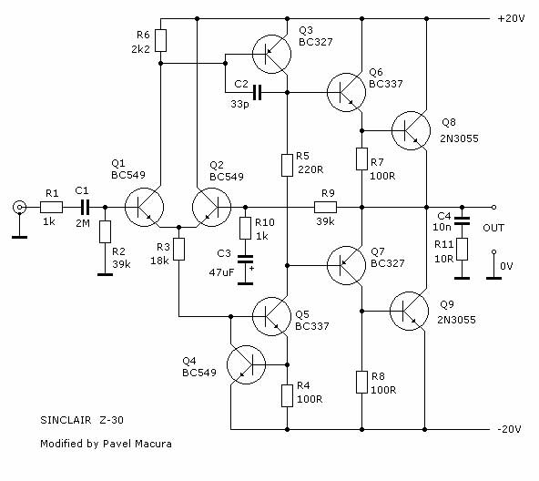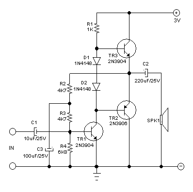

#2n3055 pass transistor schematic full#
If something is not wrong, you will have the full power 3A, which is talented enough to, show you how. More Power supply circuits How 741 OP-AMP Power supply Work In particular, Position legs of diodes, electrolytic capacitors, transistors, IC1. If you are a beginner must check and check, before entering the power, should review several times. The Q1 should be held on a large heat sink. Place position equipment according to the circuit. I may solder the components onto the perforated board. PCB, Heatsink, and others… Build 3A adjustable voltage regulator IC1: LM317T, 3 terminal positive adjustable regulator You can add more voltage range with some resistors at the S3.ġ.5V, 3V, 4.5V, 5V, 6V, 9V LM317 Selector SupplyĬ2-filter capacitor eliminates the power spike voltage before comes to LM317.Ĭ6-capacitor filters DC voltage to smooth better, low noise. 0-30V 3A Variable Regulator using LM723.As we twist the voltage selector switch, S3/2 disconnects power from the output. We use this type of switch to reduce the problem of maximum output voltage. The S3 is a 2P4T 2 Pole 4 Position Rotary Switch Selector.

You can rotate S3 to select voltage out of 3V, 6V, 9V, and 12V. We often use the same does not change For example 9V, and 12V to uses it instead of a battery. My first LM317 Variable Power Supply (1.2V to 30V at 1A) We can rotate the variable resistor-VR1 to change the output voltage, from about 1.25V to 20V. When we switch the S2-selector to the fine mode. The circuit has two options you can choose.

When Q2 conducts, the high current will flow its collector and emitter to the base of Q1, the power transistor.
#2n3055 pass transistor schematic driver#
The voltage across R1 causes a current biased to Q2, driver transistor. What can we do? To increase it up! We help it with the transistors.Īnd R1 limits current to IC1. But as we know LM317 can power out of 1.5A. The current boosting circuit for LM317Ībove I said the circuit can power the 3A output current. It will make the output voltage is very steady. The IC1 is the main, DC variable voltage regulator IC, the famous LM317. Then, the unregulated voltage comes to an input of IC1 through R1. And the R6 limits the current to save LED1 Next, the capacitor-C1 filters which becomes the pulsed DC. Then, the AC18V comes to a diode bridge-BD1, to rectify ACV to DCV, pulsed DC. T1- The step-down transformer converts AC-main to the low ACV, 18V at 3A current.

F1-0.5A fuse to protect the circuit when overcurrent.In the 3A adjustable voltage regulator circuit above.įirst of all, get an AC main to the circuit. Related Posts Working of 3A Adjustable voltage regulator circuit LM317, 3A adjustable voltage regulator circuit diagram


 0 kommentar(er)
